
Numerical Modelling of Thin Shells
Researchers
Gianfranco Canales
Lee Wilson
Narravula Harsha Reddy
Sergio Pellegrino
Description
Packaging and Deployment of Creased Thin Film Sheets
Thin-film structures are an important component of many lightweight space systems, including deployable sunshields, inflatable structures and especially gossamer spacecraft that utilise solar sails. One key feature all these applications share is the need to be packaged into a tight configuration for launch, and this introduces a large number of creases into the film. These creases can greatly affect the film properties and how it behaves once in space. Of particular interest are the loads required to package and deploy these systems, and their final shape once deployed.

Above: Wrapping and unwrapping simulation of a thin-film sheet around an eight sided hub. The black lines represent creases that allow the film to fold. However, during folding the thin-film must also bend and buckle, which requires finite element analysis software to capture.
Creased or origami-inspired structures are often modelled as rigid panels joined by hinges. This allows kinematics to be studied, but breaks down as the material becomes more flexible. Alternatively, other solar sail simulations have treated the film as an assembly of springs, rods and point masses. To gain a detailed understanding of the underlying behavior, models need to incorperate film bending stiffness and all the contact inherent in elastic origami structures. Here we are taking a more detailed approach, and model the thin-film with shell elements in finite element packages such as LS-Dyna and Abaqus. The creases are treated as lines of zero-bending stiffness. We then use forces and boundary conditions to fold elastic origami structures such as solar sail models. With this approach we can capture the contact during folding and deployment, the structural equilibrium configurations during deployment, as well as predict the forces required to deploy and unfold the structure.
Tension-stabilized Coiling of Tape Springs
Packaging and deployment are central to the design of large spacecraft structures that must fit in volume-constrained launch vehicles. Various methods of packaging and deploying involve complex mechanisms and often require electric motors. A recent approach makes use of the elastic strain-energy stored during packaging to deploy thin shell structures. Realizing in full the potential advantages of mechanism-free deployable structures requires a deep understanding of the coiling behavior of thin shells, which have been shown to exhibit unexpected localization, leading to complex deployment and potential damage. We studied the coiling behavior of a prototypical strain-energy deployed structure: an isotropic, linear-elastic tape spring---a thin cylindrical shell with circular arc cross-section.

(a) Initial configuration of coiling numerical simulation. Two localized folds are introduced, and the temporary cylinders are then removed. The results are shown in (b) for a coiling ratio of greater than 3 and (c) for r/R < 3.
The minimum force depends on the coiling ratio, defined as the ratio between the transverse radius of the tape spring and the radius of the cylinder. It varies with an inverse quadratic relation for coiling ratios smaller than 1 (bending-dominated regime) and with a linear relation for coiling ratios greater than 3.424 (tension-dominated regime). For coiling ratios between 1 and 3.424 there is an intermediate behavior, and the required tension force is non-unique and rather small.

Comparison of force vs. extension for coiling experiment and simulation
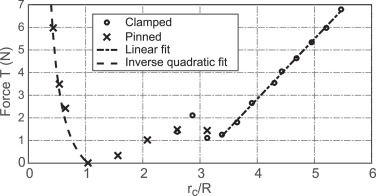
Minimum tension force required for a tape spring to fully conform to a coiling cylinder
Isogeometric Analysis for Thin Shell Deployable Structures
Thin shell structures are very sensitive to geometric imperfections, and finite element approximation of curved shell geometries introduces geometric imperfections because of inexact spatial discretization. Standard thin shell elements are formulated using Lagrange polynomials which make discretization errors inevitable. Very fine meshes are needed to reduce the effect of these errors thus increasing the computational costs.
Isogeometric analysis (IGA) uses the same functions to approximate both the deformation of a shell and its initial geometry. Irrespective of the size of the mesh, the geometry of the shell is defined almost exactly, even for the sparsest choice of variables, thus greatly reducing the errors related to shape discretization. Past research shows that NURBS-based analysis converges to accurate solutions and, in many cases, with fewer degrees of freedom compared to finite element analyses based on Lagrange polynomials. However, so far there has been no comparison of computational effort nor has there been any application of NURBS-based analysis to thin shell deployable structures. We filled this gap by studying the opposite-sense bending of a tape spring.

Convergence analysis using the type-16 shell elements of LS-DYNA---fully integrated, 4-node, bilinear flat elements. The converging solution for 40×15 mesh takes 23s of CPU time.

Convergence analysis using the reduced integrated NURBS-based shell elements of LS-DYNA. The converging solutions for 50×10 biquadratic mesh and 50×10 bicubic mesh take 76s and 146s of CPU time, respectively.
IGA converges for fewer variables but is much slower compared to the standard finite element analysis. Switching now to IGA to study thin shell deployable structures would be premature.
Reduced Order Modelling of Thin Shell Structures
Various reduced order modelling techniques (ROMs) have been proposed in the literature. However, there has not been any attempt to apply those techniques in the analysis of thin shells structures with instabilities or bifurcation points. Various ROM techniques fail when applied to the study of opposite-sense bending of a tape spring due to being a highly demanding test case. We are currently investigating computationally efficient ROM implementations for this test case.
Publications:
Reddy, N.H. and Pellegrino, S. (2021). Time-efficient geometrically non-linear finite element simulations of thin shell deployable structures. SciTech 2021, AIAA.
Wilson, L., Gdoutos, E., and Pellegrino, S. (2020). Tension-stabilized coiling of isotropic tape springs. International Journal of Solids and Structures 188-189: 103-17.
Ota, N. S. N. , Wilson, L., Gay Neto, A., Pellegrino, S. and Pimenta, P. M (2016). Nonlinear dynamic analysis of creased shells. Finite Elements in Analysis and Design, 121: 64-74.
